button. Then click Calibrate to perform the axial mapping.
| General Information |
| Recommended Sample Dimensions |
| Installing the Geometry and Loading the Sample |
| Recommendations for Setting Up the Test Procedure |
| Equations |
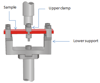
Clamped three-point bending holds a solid rectangular sample in a horizontal position. The support frame on the motor grips the sample ends, while the transducer clamp grips the center of the sample. Select the small frame with medium clamp when using the clamped three-point bending tool. Note that the length is pre-set.
The following are the available frame and clamp sizes for the clamped bending single and dual cantilever.
Frame = 34 mm
Clamp = 2 mm
Frame = 34 mm
Clamp = 2 mm
To prepare samples that fit within the physical constraints of the geometry, the following are the recommended sample dimensions.
The suggested sample dimensions give the recommended range for sample geometry based on the limitations of the size of the test geometry. Not all samples should be tested at the maximum geometry. Extremely rigid samples with a very high modulus (such as highly-filled polymers or reinforced composites) may require a more modest geometry to obtain an instrument operating range where useful data can be expected. A single point test using the desired geometry should be used to fine-tune sample parameters and geometry selection. If too much force is required or the measured strain is significantly lower than the commanded value (which indicates that the transducer compliance may be too large to accurately correct), the sample should be made thinner, narrower, or longer to obtain better results. If the sample still cannot be tested practically, it may be necessary to use a different testing geometry, (such as three-point bending or mixed bending) for very high modulus samples, or a tensile geometry for very thin or low modulus sample.
The ETC is a radiation oven with the solid sample and temperature probe in different locations - thus the actual temperature of sample and probe may be different. The difference varies with the sample thickness and the applied heating rate. In this case the furnace temperature needs to be calibrated in order to monitor the correct sample temperature.(see: Offset and Span Calibration for DHR/AR)
button. Then click Calibrate to perform the axial mapping.
Refer to the figure below for an illustration of the geometry with a sample loaded.
button to align the upper test fixture.
- For single cantilever, tighten one outer clamp.
- For dual cantilever, tighten both outer clamps.
4. Once sample has been fully tightened, adjust stage position to obtain a Normal Force meter indication of zero or activate axial force control to adjust the static normal force to zero.(see also Axial Force Guidelines).
The figure below shows a dual cantilever configuration:
Strain Constant
|
Stress Constant
|
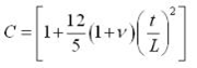
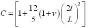
Shear Factor
|
|
VariablesW= Width of sample T= Thickness of sample L= Length of sample |
|
Strain Constant |
Stress Constant
|
Shear Factor
|
|
VariablesW= Width of sample T= Thickness of sample L= Length of sample |
|